Solidworks Stress Reference

Hi all

My problem is the following:

*A rolled sheet metal (thickness: 1.5, rolling diameter 1000)
(In fact, it doesn't matter, this part would be a cylinder, it would amount to the same thing).
*Flat-head screws.
The sheet metal is pierced with about fifty holes.

I want to use the stress references to place a screw in each hole automatically.
Each screw must be concentric to the drill and the flat head of the screw must be tangent to the outside of the bent sheet.

I can't do it.
I own Solidworks 2024 Education.

A little help would be very useful.

In the meantime, I wish you a pleasant day

Jeanartemis

Hello, wouldn't a repetition of components be suitable in your case?

1 Like

Hello.

In fact, it all depends on how your 50 holes are made

If they are done by repeat, then you can use the " Repeat-driven component repeats" function in your assembly

image

If you made them with points in a sketch, then you can use " sketch-driven component pattern"

As I told you, it depends on your creation of the holes. Can you tell us more about this?

2 Likes

Thank you for answering me.

In fact, when inserting one or more screws, I manage to create a concentricity for each hole/screw but I can't get the tangency.
There must be a problem in the constraint reference...

Hello;
Normally, if your holes are made with the Drill Wizard, you should be able to use the " Function-Driven Repeat/Repeat " function.
In this case, you will only have to correctly constrain a single screw and set the point of origin of the repeat.
https://help.solidworks.com/2022/French/SolidWorks/sldworks/HIDD_DVE_COMPPAT_DERIVED.htm?verRedirect=1

2 Likes

If your holes are made on the flat of your sheet, it will generate ellipses during the bending, I advise you to use the sketch point to create the coaxiality constraint.

I don't know about repetition driven by a repetition.
I'll look at that side

I don't know about function-driven repetition.
I will focus on that.

thanks for the link...

The drills are made after the bending...

Are your holes material removal or did you create them with the drilling wizard?

Drilling assistance

I can attach the sheet metal file and a rivet (or screw) for example

The holes are made with the drilling assistance

To facilitate your constraints of your rivets or screws on cylindrical components, I advise you to create " Reference Geometries" (in particular points, planes and axes) on your fastener elements.
This avoids the constraints of tangencies which are never very stable...
https://help.solidworks.com/2022/french/Solidworks/sldworks/hidd_dve_refpoint.htm?rid=137600

I will look at this at the end of the afternoon.
I have to be away for a while.
I'll get back to you very soon.
A big thank you...

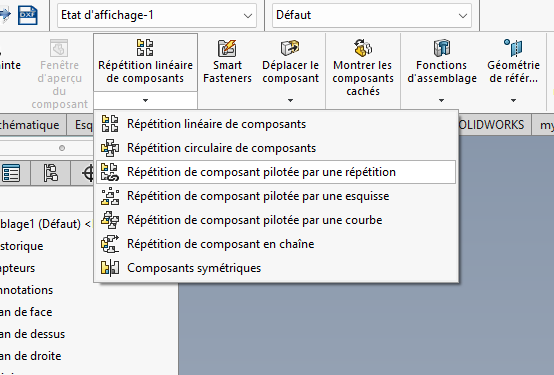
Totally agree on this point, the tangent constraints are the same...
Possibility of making the hole via drilling assistance with 3d sketch on the outer shell of the cylinder then circular drilling stress and stress on the 3d sketch point (from the drilling assistance.
And finally repetition and repetition driven as mentioned by @coin37coin and @Maclane .

1 Like

Oh my, that means a lot to me.
I've never used that.
On a flat surface I don't have a problem, when I insert screws, they are positioned one after the other on each hole on which I present them.
On these screws I put a constraint reference and everything is fine.
On the other hand, if I do the same thing on a non-flat surface, nothing works.
I retain the idea of repetition driven by a repetition.

The piercings that are made are not always repetitions. Sometimes they are arranged according to the assembly in an irregular way.

I don't understand when you say " circular constraint of the drilling and constraint on the 3D sketch point (of the assistance for the drilling "...