Bonjour,
Auriez-vous un moyen ou des astuces et des techniques pour simuler des aimants dans Solidworks ?
Sinon, comment feriez-vous ?
Bonjour,
Auriez-vous un moyen ou des astuces et des techniques pour simuler des aimants dans Solidworks ?
Sinon, comment feriez-vous ?
Bonjour,
J’imagine qu’il s’agit de Solidworks Simulation…
A ma connaissance, il n’y a pas de solution pour appliquer un champ de force volumique dans SW Simulation. Sauf la gravité et les effets dynamiques dans un mouvement de rotation.
Quelques précisions seraient utiles : statique ? Sur une pièce, un assemblage ? Quelle distribution pour le champ de force volumique ? des aimants ou un aimant ?
Bonjour @m_blt
Peu importe le moteur, flow sim, sw simulation, ou même tricher pour arriver au même comportement.
Mon but est principalement de simuler leur répulsion et leur attraction selon leur polarité et leur force, en particulier lors d’un glissement, et ce en fonction du poids qu’ils ont sur les épaules.
C’est pour créer une étude de mouvement qui exprimerait le décalage des pièces aimantées flottantes quand elles croisent les polarités identiques.
Il doit y avoir des logiciels dédiés (pour ceux qui font des moteurs électriques par exemple).
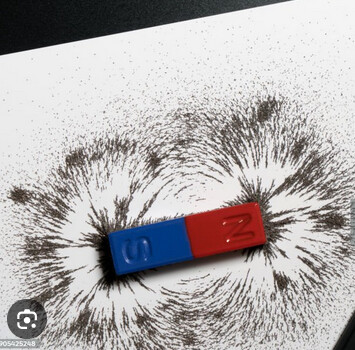
Ton désir est loin d’être le plus simple car les zones de transitions vont beaucoup dépendre du type d’aimant et d’effets de bords sûrement bizarre (arriver à placer les aimants comme tu veux risque déjà d’être coton) : la simple expérience aimant/poudre magnétique montre déjà que le champ magnétique n’est pas régulier et là tu va superposer plusieurs champs…
il y a je crois un module pour la simulation magnétique, oui, non, peut ^tre?
un oscilloscope pour bien les positionner?
Sinon voir avec ton fabricant d’aimant qui te fera la simulation?
Quand on n’a pas une compétence, voir avec le fabricant qui dispose normalement d’une palette technique sur le sujet.
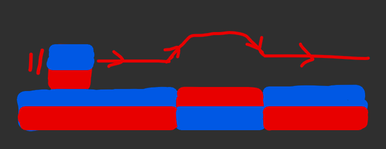
Je ne peux pas trop parler du projet mais voici une animation de ce que j’aimerais calculer/mesurer : l’amplitude de mouvement vertical des pièces jaune et verte. Variant selon le poids sur le dos de la verte.
Les aimants sont, pour l’heure, des néodymes N35 de 3x3mm.
Bonsoir @Sylk ,
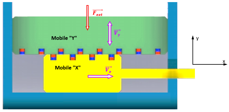
Enfin quelques données : une structure sous la forme d’un schéma, et les dimensions des aimants (section 3x3 mm)…
Les aimants ont de très petites dimensions, et selon le modèle de comportement retenu, l’effort d’attraction/répulsion varie en 1/r^2 ou en 1/r^3. Une simulation doit être possible sur la base d’une de ces approximations, et du schéma ci-dessous.
Mais s’agissant d’un problème de dynamique, les paramètres des éléments du système autres que les aimants ne sont pas sans effet sur le comportement.
A défaut de révéler l’intégralité du projet, il faudrait fournir quelques données complémentaires, au moins des ordres de grandeur…
Espacement entre aimants ? Je propose 10 mm.
Vrai / Faux
Effort maxi d’attraction/répulsion (décollement de deux aimants en contact N/S) ?
Nombre d’aimants sur chacun des deux mobiles ? Je propose 8 et 4, comme sur le schéma.
Vrai / Faux
Masse du Mobile « Y » en déplacement suivant y ? Je propose 1.0 kg.
Vrai / Faux
Le schéma est-il une vue de profil ( axe y vertical) ou de dessus ( axe y horizontal) ?
S’il est vertical, le poids du mobile « Y » intervient dans son mouvement. Sinon, pas d’influence de la pesanteur.
Y a-t-il un effort extérieur supplémentaire sur le mobile « Y », suivant y ?
Oui / Non
Si oui, constant ou non ? Quelle valeur ?
Loi de déplacement du Mobile « X » ? Je propose un mouvement uniforme (environ 40 mm ?), en un temps de 1 seconde ?
Vrai / Faux
Amortissement ? Vrai / Faux
Frottement ? Vrai / Faux
Ouf…! 
Bonsoir @m_blt merci pour ta réponse.
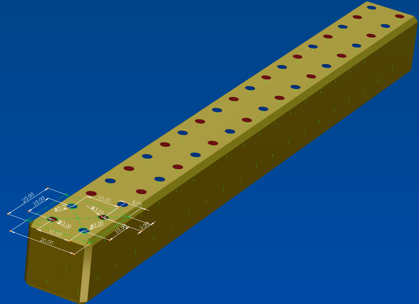
Espacement entre les aimants de 10mm (5mm des bords): VRAI
Le nombre d’aimants par mobile est doublé par rapport à l’illustration car c’est une vue en coupe ; au 1er plan de chaque aimant il y en a un autre.
Ce nombre est très variable, dépendant de la longueur du mobile Y, qui peut aller de 4 aimants (2x2 donc) pour 20mm de large à 40 aimants pour 200mm.
Aimants compris, le poids du mobile Y peut varier de 7 à 1218 grammes.
Sachant que le poids sur seulement 4 aimants peut aller de 7 à 1127gr (161x7), et sur 40 aimants aller de 70 à 1218gr (174x7).
Schéma vu de profil, déplacement en y pour le mobile Y donc influence de la pesanteur : VRAI
Effort extérieur supplémentaire en y : NON
Constance et vitesse de mouvement du mobile X en x extrêmement variables car manuel.
Amortissement : FAUX
Frottements : VRAI difficilement quantifiables mais limités autant que possible (le proto sera en impression 3D fdm, en jouant sur l’orientation des couches).
Un cas extrême des « 1127gr sur 4 aimants » est celui qui aura le plus de friction de par son porte-à-faux, tandis que le cas « 1218gr sur 40 aimants » aura une bien meilleure répartition des masses et donc très peu de friction.
Il y a beaucoup d’inexactitudes dans mon illustration ; le but était plus de montrer ce que je voulais dire en parlant de décalage, pas d’être exact. J’en referai une je pense.
Les principales sont qu’en réalité la largeur du mobile X ne peut avoir qu’une taille ; toute la largeur du contenant, soit 200mm et 40 aimants. Et que sa languette ne sert qu’à sortir totalement le mobile X du contenant, ouvert sur le côté.
Les poids annoncés peuvent changer. Le mieux c’est que la valeur min (7) soit une variable, les valeurs max n’étant que des multiples de la valeur min.
Je ne sais pas si ça aide tellement plus, mais ça devrait aider à ébaucher la « simu ». Difficile de pas trop en dire sans en dire trop. ![]()
Bonjour @Sylk,
L’attente fut longue, mais pas vaine : une macro VBA destinée à simuler la dynamique des deux coulisseaux ‹ X › et ‹ Y › influencés réciproquement par les champs magnétiques des rangées d’aimants.
Macro conçue d’après mon interprétation du schéma animé et des indications des messages précédents. Pas certain que ça reflète la réalité du projet compte tenu du coté obscur de certaines informations :
Sans doute clair pour l’auteur, beaucoup moins pour le lecteur que je suis…
Impératif: l’appli nécessite de disposer d’Excel pour l’affichage des résultats de la simulation et leur sauvegarde.
Macro développée avec VBA Solidworks de façon à permettre l’animation du modèle géométrique SW.
Installation: décompacter le fichier Aimants.zip joint dans un dossier accessible en écriture.
Ouvrir Solidworks et charger le document d’assemblage AxeNumérique.SLDASM situé dans le dossier d’installation (SW 2022).
Lancer la macro Aimants.swp, de préférence après avoir lu le document Aimants.pdf.
A utiliser sans modération, en gardant à l’esprit le fait que les garde-fous sont rares.
Aimants.zip (83,7 Mo)
Bonjour @m_blt franchement pour une réponse de cette qualité j’aurais même pu attendre 1 semaine de plus ![]() MERCI
MERCI
J’en attendais pas tant, mais pas moins venant de toi. Bravo.
Malheureusement je ne peux pas profiter de l’assemblage et des pièces car je suis en 2020, j’aurais pu le préciser mais j’avoue que je ne m’attendais pas à une réponse aussi complète avec un assemblage en prime. Ça t’aurais peut-être épargné du boulot, mais j’imagine que c’était de toute façon utile pour toi pour que tu testes ta macro.
Je ne suis pas certain d’avoir bien compris la façon de modéliser les coulisseaux décrite dans ton PDF (un bijou ![]() ). Plus précisément les aimants.
). Plus précisément les aimants.
Actuellement je crée une paire d’aimants (2x 2paires puisque sur 2 rangées en z), chacun orienté différemment, et applique une répétition. Mais si j’applique une répétition avec nbAimants lié au nombre de répétitions, et Intrvl lié à l’espacement entre les paires (qui vaut 2 fois l’espace entre 2 aimants d’une même paire), ça ne va pas le faire, je vais me retrouver avec nbAimants = à la moitié d’aimants, et Intrvl = au double de l’espacement entre 2 aimants.
Ta vidéo montre correctement les 2 rangées, mais je pense que je me suis mal exprimé concernant leur orientation (je ne l’ai pas précisé du tout même). Ça ne change rien au résultat du calcul mais plutôt à leur modélisation. Bien que techniquement, si je ne cherche que le résultat je peux les modéliser avec ces orientations. Pour la présentation c’est plus gênant.
Le coulisseauX serait plutôt comme cela :
Encore un énorme merci pour ton aide !
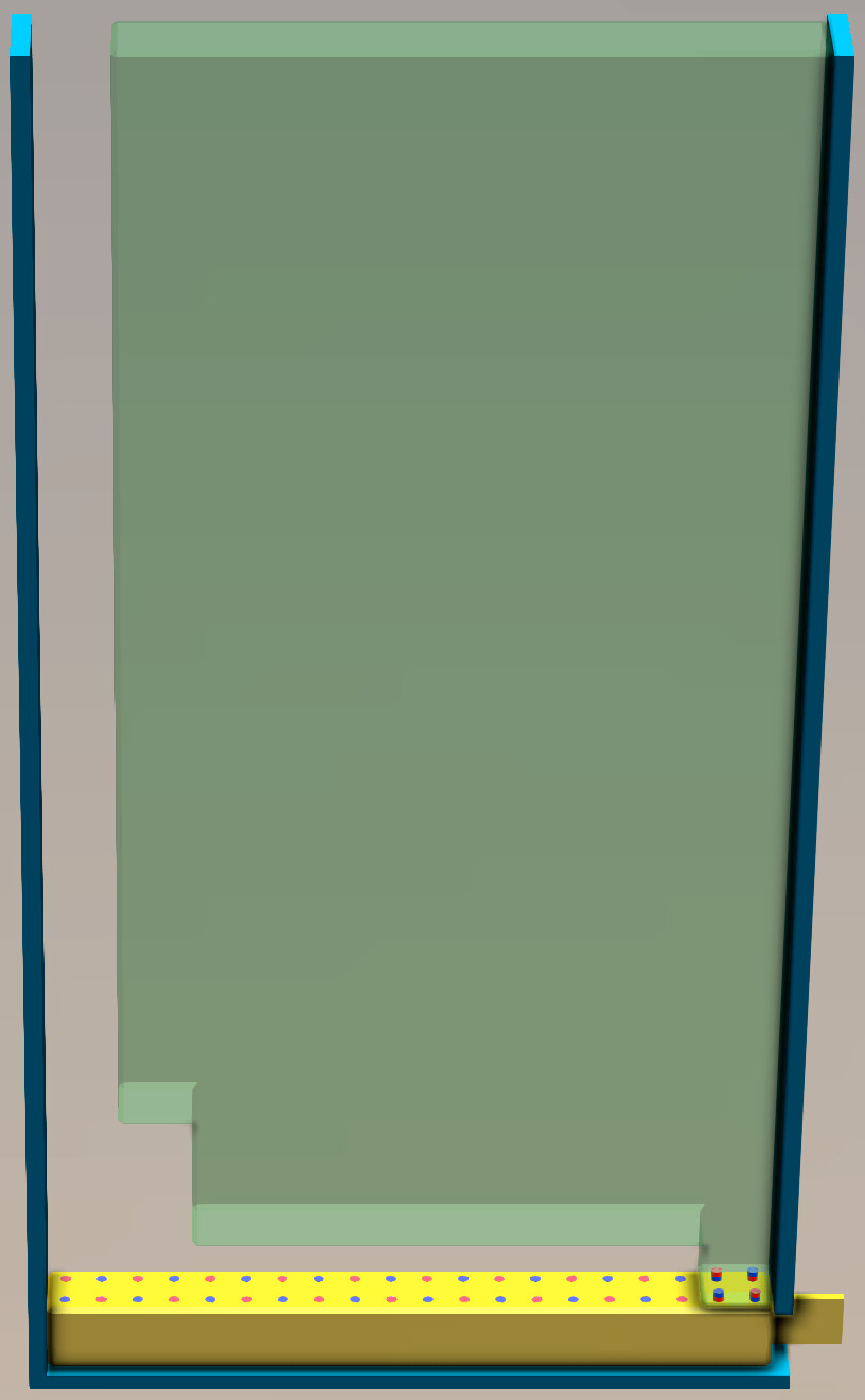
Pardon, voici les illustrations de mes propos obscurs.
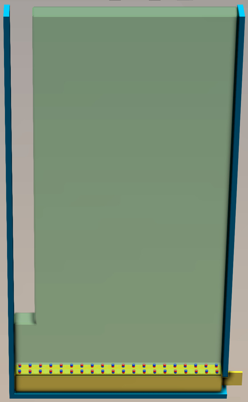
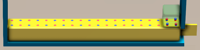
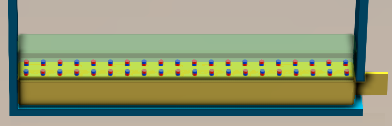
(1) Le cas extrême en question, en vert, le plus lourd sur le minimum d’aimants, 1127gr sur 4 aimants. Et (2) le cas le plus lourd sur un maximum d’aimants, 1218gr sur 40 aimants :
(3) Le plus léger sur un minimum d’aimants, 7gr sur 4 aimants.
Et (4) le plus léger sur un maximum d’aimants, 70gr sur 40 aimants :
Avec ces images, je comprends mieux. C’est à l’inverse de ce que j’imaginais.
Ceci étant, si on considère la configuration 4 aimants, la masse à soulever peut varier entre un mini de 7g et un maxi de 1127 g.
Si ce sont les mêmes aimants dans les deux situations, et qu’ils sont capables de soulever la masse maxi, il vont « satelliser » la masse mini : effort nettement supérieur à 11 N pour soulever la masse maxi (disons 30 N) et masse faible (7g) = forte accélération.
Vieux souvenir d’un cours de méca : F = m a . Soit une accélération initiale de 30 / 7e-3 = 4300 m/s².
Un méchant coup de pied. Heureusement il ne dure pas longtemps et il y a probablement une butée (cf. ymax)…
Ci-dessous le document de l’assemblage utilisé pour mes tests, en version SW2020.
Récupéré de l’original en Parasolid, et sauvegardé en sldasm depuis une version 2020.
Plus de contraintes, plus de géométrie native, mais globalement l’animation fonctionne.
AxeNumeriqueSW2020.zip (12,7 Mo)
Ce sont les mêmes aimants dans toutes les configs.
D’après l’échantillon partiel que j’ai en main, avec du N35, il ne devrait pas décoller trop haut.
Même si j’avais considéré qu’on pouvait négliger les frottements, il est évident que de « tracter » le mini coulisseauY vers la droite en tirant le cX créera une certaine friction entre la paroi de droite et la face droite du cY, en plus de rendre son inclinaison potentielle plus sujette à augmenter la friction (car l’angle de la diagonale est plus grand sur une petite surface), et donc d’agir comme un frein naturel. En plus des « encoches » qu’il y a côté parois qui pourraient bien faire office de butées.
Et puis la hauteur du contenant est tout de même importante, je doute qu’il en soit éjecté. Il y a aussi un autre aspect non communiqué contribuant justement au « confinement » du système et qui en l’occurrence dépendra des résultats de cette étude, et une des raisons pour lequel je cherche justement à la simuler.
Ça reste tout de même un point à surveiller.
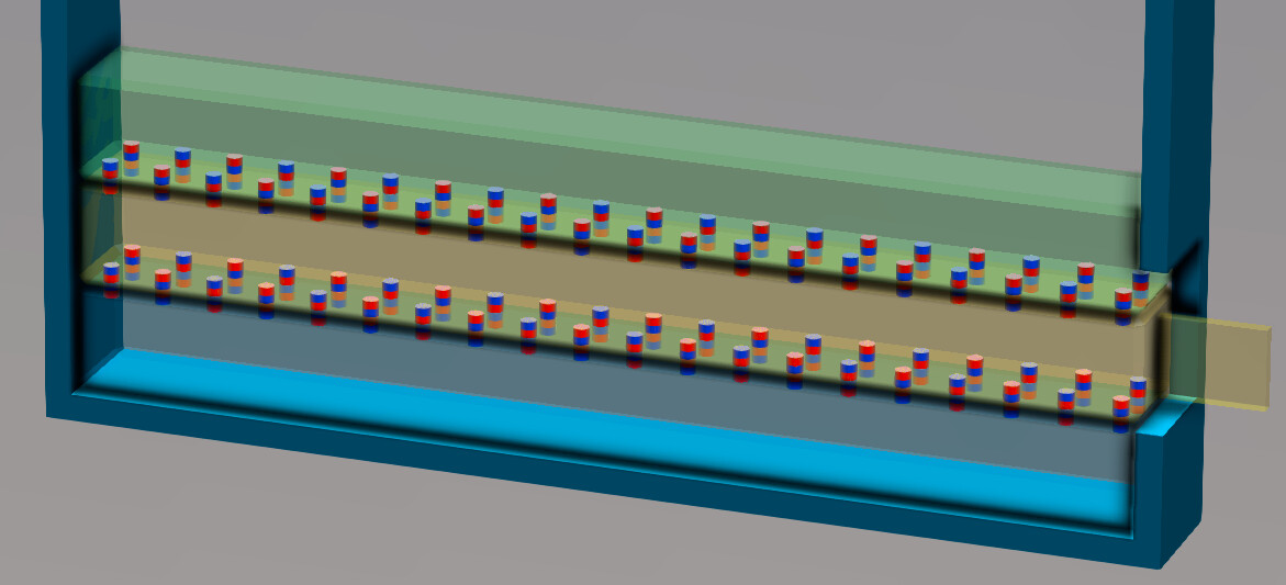
Je vais étudier tout ce que tu as fourni, en espérant pouvoir l’étendre au cas du coulisseauX intercalé entre 2 coulisseauY (dessus) et Y’ (dessous), illustré par ma 1ere animation.
Je dirais que la répulsion sous cX est fonction du poids cumulé de cX et cY ainsi que de la répatition des aimants de cY’. Avec décroissance progressive liée à l’extraction de cX.
C’est noté.
Un dernier mot : ne pas hésiter à augmenter le nombre de points dans la situation du méchant coup de pied. Ou réduire la durée de simulation.
Et une dernière question : pourquoi pas un galet sur une rampe ondulée pour une meilleure maîtrise des déplacements ?
Mais disons que l’intérêt est précisément de connaître quelle force max sera à contenir entre cX et cY. Le but premier de cette étude étant d’insérer une sorte de clapet entre les coulisseaux, qui empêcherait cX de monter, mais l’épaisseur de clapet exploitable étant très faible, il est très flexible et je cherche à évaluer sa déformation. Et le cas échéant, des moyens de le renforcer. J’aurais certainement dû commencer par le préciser mais disons que je voulais savoir dans quelle mesure je pouvais me passer de clapets…
Je pense donc que l’étude du cas (5) est le plus pertinent à considérer.
Je vois ce que tu veux dire mais c’est impossible sur ce projet.
Ce serait tellement plus simple d’en exposer la totalité…
Quand je reviendrai sur ce projet, j’aurai des questions sur l’utilisation de ta macro @m_blt , notamment s’il est possible de trouver les caractéristiques de l’aimant d’après son volume et sa catégorie, car je n’ai pas trouvé les specs qui me permettent d’être sûr que j’ai les bonnes valeurs pour la simulation.
En attendant je valide quand même ta réponse parce qu’elle répond clairement au problème.
Merci encore pour ton implication !!
projet/idée très intéressant(e)!!!