Thank you for looking at my parameters, I'm stuck on the interpretation that deviates from my calculations... The constraints given for the cords, if I make an exploitation of his apothem, from the connector, as his is more important, I integrate although the constraint is weaker to oppose the initial force (the latter does not change, this is my initial data). Kind regards. TD N°2.7z (31.9 MB)
Good! Ouch! I am going to have to tell you again that this is not right! Sorry!
I think that before you want to do triple backward jumps in SW followed by a Tail grab followed by a back flip, you need to better understand how SW simulation works.
Meanwhile
If your goal is to test the equivalent of weld seams, you have to do it differently.
1°) As you have put the interactions between the components, it would be equivalent to having a single part that would be created in a single volume. As a result, you will never be able to see anything on the cords.
2° For the previous problem of the apothem, I suggested that you put a space between the two welded pieces, but I see that you do not take this suggestion into account. It may sound silly but it's the only way for the simulation not to glue the two decks together and consider it as a single volume.
Small problem I am in 2022 version so I cannot send you my results. As you are students and nice, I will make you a little video, you will have it in the afternoon.
For the comments between the simulation and the manual calculation I let @m.blt explain to you because he is a teacher and will be able to explain to you better.
In component interaction I chose free, is this my mistake? Thank you for the help, attached is a PDF of apothema search on a lifting ear for a tank, with screenshots of my cords. Kind regards.
Note that I don't answer your question which is to compare the results of the theoretical calculation and the calculation from the simulation (nice zozo!)
I was especially interested in showing what happens at the level of the cords because what is important is to understand the material. Incidentally, it is possible to use simulation with certain parameters and results.
With the help of your video, you give me the framework to follow to understand the installation of a weld bead in an assembly (or leave a functional game, I was in balance to use a virtual wall, but you don't use it, I can know the configuration of the link contacts:
first we remove the link given by the assembly (OK, NOK) -in second contact no penetration of the two parts (OK, NOK)
For volume cords, which option to use?
no penetration (OK, NOK) -solidarity (OK,NOK)
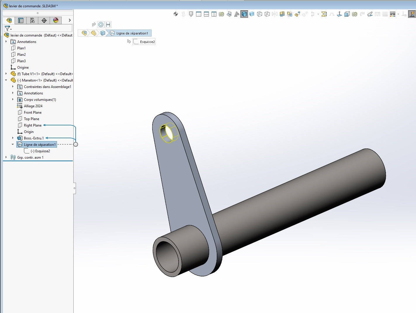
. I had discussed the search for bending on a pivotal link axis on the forum and the use of the separation line was the recommended tool to use.
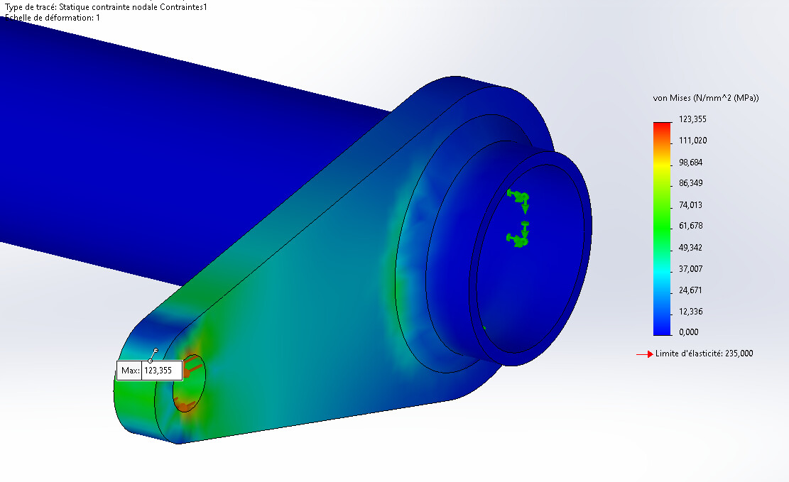
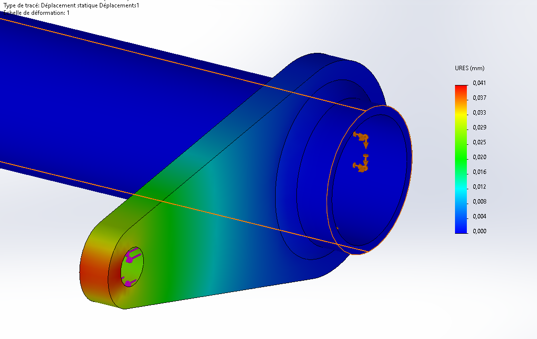
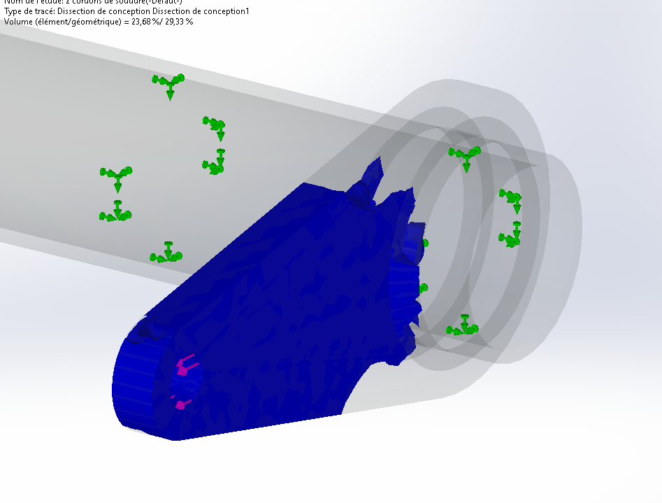
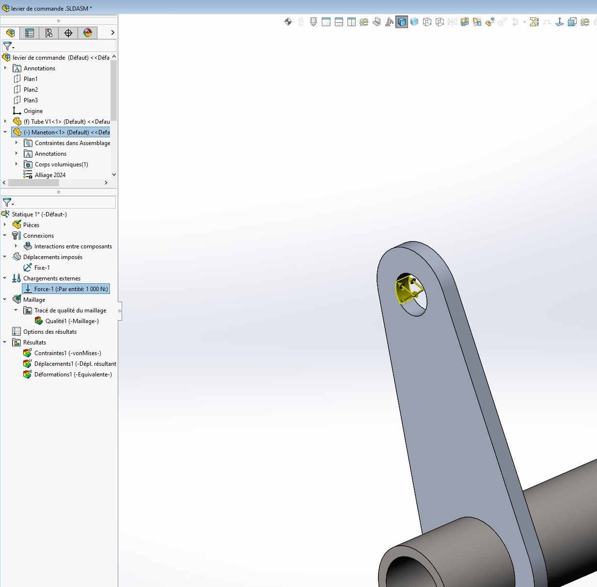
I didn't know about design dissection , but here, it's very demonstrative about the extent of the constraints within a localized area, with a hidden base. Thank you for this visualization tool. No problem with my desire to cross the results by hand and the connector, I had used the connector only to have stress reactions, but with your volume approach I can probe the critical area and reassure myself about the hold mechanics. The calculation approach is to start from the surfaces of the sheared bead and not to exceed the weld stress, it is an imposed data that informs me of the length of the compatible beads. Your demonstration allows me to better perceive the behavior of the cord, it was my initial request, I am happy to have an additional tool in my box! Thank you In the case of combined loads, the spillage is instructive.
Some thoughts in the attached document, based on your model of mechanically welded plates. The idea was to compare the " solid cord approach" with the " connector " approach of the SolidWorks EF simulation module.
The conclusion in two words: a certain convergence of behaviours, with differences of around 10%. And the suspicion of a singularity in the volume approach, which makes the analysis of the results delicate.
As for comparing the results of these simulations to those of a " manual " (in fact theoretical) approach, I find it hard to imagine... In particular, what answer should be given to the question: how to evaluate the distribution of forces in weld seams, an essential prerequisite for an evaluation of stresses? Perhaps the Eurocode gives some information on this point, but I do not know enough about it.
I have just read your analysis and it directs me more towards the use of forces in the cords. Depending on the approach used, the convergence of results provides a good idea. Concerning Eurocode 3, I am not a specialist in this standard, however by applying it I find the values of the calculation notes. The parallel tau is validated (close value) on the other hand the sigma is never in the measurement range of my tests, so I will follow an analysis from the forces and it already suits me very well, thank you for the work done and the remarks/advice, attached a calculation note and a Eurocode 3 supplement (the cords), my base used. Kind regards.
1°) Solidworks and Simulation are two totally different applications. as a result, static simulation does not care about the constraints of SW CAD. It uses the pre-positioning of the parts between them and depending on your parameters will manage the contacts in one way or another.
By the way, you will notice that the first action it takes is the management of contacts, it will analyze all the contacts (at nodes) between each room.
Depending on the criteria and simulation parameters, it will or will not allow interpenetration between the parts "for example, the old function without penetration made it possible to have a gap between two parts of several millimeters. If, under the effect of the forces imposed, these pieces ended up coming together, then touching each other without being able to interpenetrate. I have seen too often in the version below 2021 people focus on the 'No penetration without having understood what I have just explained about the management of global contacts.
So answer to questions 1 and 3 = KO For question 2, the cord in the case of your assembly is considered a triangular piece in contact with the two plates. If you have set at least two constraints, you don't have to worry about them. It is the management of contacts at the nodes that will manage.
On the other hand, a little advice, if one day you make mechanically welded frames with parts other than welded profiles, check that all the parts are with constraints (therefore with contact).
I have the 2022 version, see if you can have the 2022 student version, it will be simpler if you have other questions afterwards.
Thank you for your informative document on several points. I have read your document carefully except that I do not find the same values as you (strange). Could post your ASM in pack and go so that I can compare our two versions and settings.
How do you manage to have the two representations on page 3 (I don't know).
I put forward a hypothesis for the difference with the connector! When there is welding (i.e. fusion of metal between the two parts plus the material of the weld, Simu no longer considers as knot-to-knot contacts between 2 parts, but as if the three parts were made in a single body (a single PRT). We could make a single piece to see if the hypothesis has any value.
A first possible explanation for the differences in values between our respective models: I reduced the external load to 2000 N. Also a collection of details in the model parameterization that can induce differences.
As for the gap between the volume model and the connector model, it does not shock me insofar as the models are different. The SolidWorks simulation module is sometimes sparse with details on the principles used.
For the illustrations on page 3, there is nothing very mysterious:
The first is a von Mises constraint plot, by checking the " Show plot only on selected features" checkbox in the " Advanced Options" area, and then selecting the faces to use for the representation.
the second is a display of the values of forces exerted at the level of a surface: " Results " options, " List of resulting forces". Select the faces or edges to be examined, then click the " Update " button. Depending on the origin of the force (external load, force between components, etc.), you must tick the right box in the " Options " area. Moments are also offered if a torsor reduction point is selected.
Hello Zozo, I also have my license for the 2022 on my desktop, not on my laptop because I can no longer make changes to a 2021 and transmit it to people who don't have the latest version in their office to be able to modify parts (in 2021), it's complicated ... To validate your method and apply your advice, I will go back to the study of my crank pin and do the two versions in the morning, plus the analysis of the forces with the m.blt sheet. I am learning new things and especially how this simulation tool has been structured by your remarks and advice from both of you, thank you.
Thank you for explaining the configuration, it's instructive and formative. Concerning the torsor (sweats listening to this word... with the risk of errors in the long run.) I will be able to change the center of reduction and place myself at the critical point, I was very interested at the first sight of the cord tracing and to note a variation of the apothem in relation to the loads and reactions this allows me to get an idea of the resumption of forces and then maybe consider a discontinuous cord, but this intuition would weaken the welded assembly I think. Kind regards.
I am very happy with the approach to follow with the play between my two pieces. Thanks for the design dissection tip, I don't know... Not good. I will be able to continue my simulations. Have a good day to you.
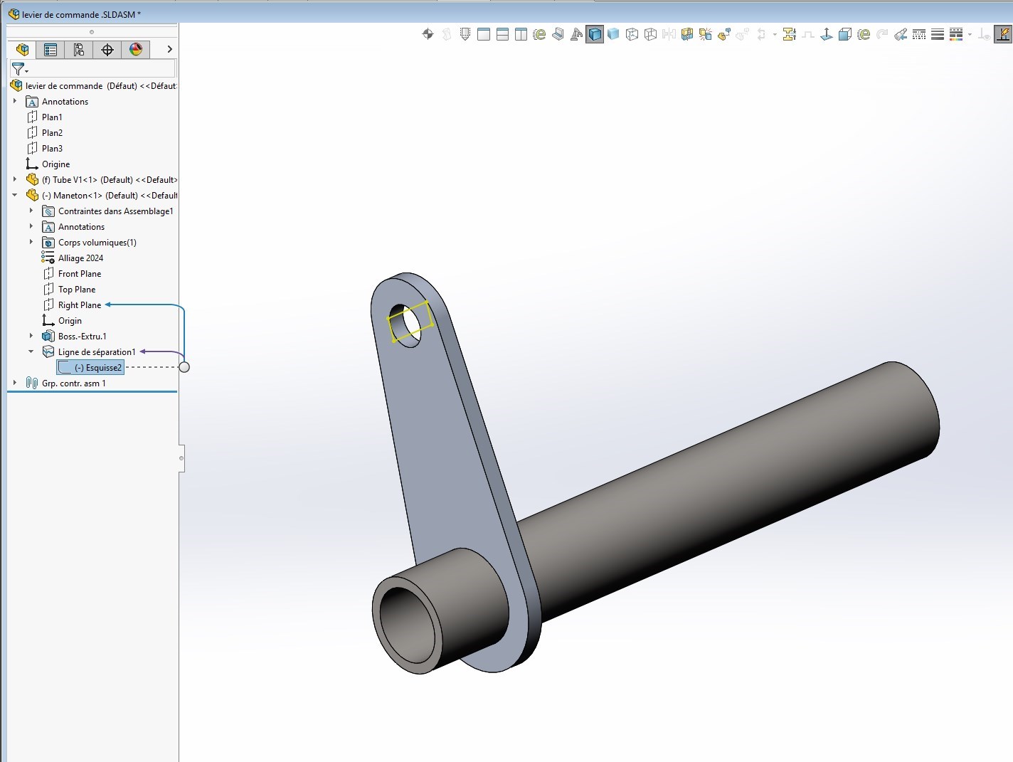
Hello Zozo_mp, Ah I hesitated to put a separation line on my bore (like a bearing load that touches 1/2 surface with the presence of the play with the shaft) because originally I had put a separation line inside my tube but by putting a shell, I had an infinite displacement ... no connection between the two 1/2 hulls well that's my personal understanding ... I am willing to look at your parameters to confirm the implementation in volume and I will stay in volume, not easy to use the solder connector because it requires a concurrent edge and with the play not possible it is necessary to make a configuration derived by a variable set =0. Ok for my mistake on the search for twisting, carelessness ... Thank you for the information and advice.
For the solder connector I think you don't need any play. I don't have too much time to look but normally connector means that it connects two elements together This means rechecking that your two pieces (without play) must be declared " free " in the interaction between components at the outset.
Be careful, a separation line allows a calculation with an approximate value because the purpose is only to measure the torsion and possible deformations of the crankpen.
This is not comparable with a " bearing load", not least because the bearings are fixed and they do not measure the same thing at all.
From my attempts, if a play is present between two elements, by the geometry the connector does not find a concurrent edge so this path is impossible from my beginner experience. What bothers me is the obligation to be orthogonal between the two surfaces, for example an element oriented at another angled angle and the connector becomes refractory! OK, it's noted and archived to have adapted tools. Thank you. Kind regards.
Your miseries on soldering is in line with my own difficulties with SW soldering.
So much so that I sometimes wonder if designers have ever set foot in a workshop that does welding. We could send them on an internship with @OBI_WAN ! It's been ten years since I gave up welding in sub-ASM and ASM, it's unmanageable and too talkative. I put the indications directly in the MEP, which is more than enough for welders who are not Mickeys and who understand very well the intentions of the assembly.